Transmission media refers to the physical or wireless communication channel used to carry data signals from one device to another within a computer network. It forms the fundamental pathway through which information is transmitted, ensuring connectivity between networked devices.
The selection of a transmission medium depends on factors such as:
- Transmission distance
- Data transfer speed (bandwidth)
- Susceptibility to interference and noise
- Cost and installation requirements
Based on the nature of the transmission path, transmission media are broadly classified into two main types:
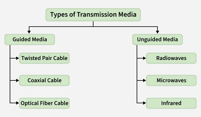
Guided Media
Guided Media also known as wired or bounded transmission media, refers to transmission media in which data signals are transmitted through a physical path using cables. The signal is confined and guided along a fixed route, providing controlled communication between network devices.
- Uses physical cables to transmit data signals.
- Provides dedicated and well-defined transmission paths.
- Major types of guided media included Twisted Pair Cables, Coaxial Cables and Optical Fiber Cables.
- Offers higher data transmission rates compared to most wireless media.
- Provides better security due to physical connectivity and limited signal leakage.
- Suitable for short to long-distance communication, depending on the cable type used.
1. Twisted Pair Cable
A twisted pair cable consists of two individually insulated copper conductors twisted together in a helical pattern to minimize electromagnetic interference (EMI) and crosstalk between adjacent pairs. Multiple twisted pairs are typically enclosed within a protective outer sheath, making this cable one of the most commonly used and cost-effective guided transmission media.
- Twisting of conductors helps reduce interference and signal degradation.
- Multiple pairs can be bundled together within a single cable.
- Widely used due to low cost, flexibility, and ease of installation.
- Commonly used in telephone systems and local area networks (LANs).
(a) Unshielded Twisted Pair (UTP): UTP cable consists of twisted copper wire pairs without any additional metallic shielding. The twisting provides basic protection against interference, making UTP suitable for environments with moderate noise levels.

Advantages:
- Least expensive among guided transmission media.
- Easy to install and maintain due to its lightweight and flexible nature.
- Supports high data transmission rates over short distances.
- Widely used in Ethernet-based LANs and telephone networks.
Disadvantages:
- Lower performance and capacity compared to Shielded Twisted Pair (STP).
- Limited transmission distance due to signal attenuation.
- More susceptible to noise and electromagnetic interference.
(b) Shielded Twisted Pair (STP): Shielded Twisted Pair (STP) cable consists of twisted pairs of insulated copper conductors enclosed within an additional metallic shielding layer, such as a foil or braided shield. This shielding provides enhanced protection against external electromagnetic interference (EMI) and reduces crosstalk, resulting in more stable and reliable data transmission.

Advantages
- Provides better performance at higher data transmission rates compared to UTP.
- Significantly reduces electromagnetic interference and crosstalk.
- Ensures more reliable and stable communication, especially in noisy environments.
- Suitable for high-speed Ethernet networks and voice and data transmission systems.
Disadvantages
- Higher cost compared to Unshielded Twisted Pair (UTP).
- More complex installation and termination due to shielding requirements.
- Bulkier and less flexible, making cable management more difficult.
2. Coaxial Cable
Coaxial Cable consists of a central copper conductor surrounded by a dielectric insulating layer, a metallic shielding layer, and an outer protective jacket. This structure allows signals to be transmitted with better protection against noise and interference compared to twisted pair cables.
- Supports data transmission in both baseband mode (single channel) and broadband mode (multiple channels).
- Provides higher bandwidth than twisted pair cables.
- Strong shielding makes it more resistant to noise, crosstalk, and electromagnetic interference (EMI).
- Commonly used in cable television (CATV), broadband networks, and analog television systems.
- More durable and reliable due to its layered construction.
- Easier to install and maintain compared to optical fiber cables.

Advantages:
- Supports higher bandwidth than twisted pair cables.
- Offers better signal quality and reliability.
- Allows multiple channels using frequency division multiplexing (FDM).
- Less affected by external electromagnetic interference.
Disadvantages:
- More expensive than twisted pair cables.
- Requires proper grounding to ensure safety and minimize interference.
- Bulkier and less flexible due to multiple layers.
- More vulnerable to security breaches, as the cable can be physically tapped.
3. Optical Fiber Cable
Optical Fiber Cable is a guided transmission medium that transmits data in the form of light signals through a glass or plastic core using the principle of total internal reflection. The core is surrounded by a cladding layer with a lower refractive index, which confines the light within the core and enables high-speed, long-distance data transmission.
- Supports very large data volumes at extremely high speeds.
- Can operate in unidirectional or bidirectional communication modes.
- WDM (Wavelength Division Multiplexer) allows multiple light signals to be transmitted simultaneously over a single fiber.
- Widely used where high bandwidth, long distance, and low signal loss are required.

Advantages:
- Provides very high bandwidth and data-carrying capacity.
- Lightweight and compact, making installation easier over long distances.
- Exhibits low signal attenuation, suitable for long-distance communication.
- Immune to electromagnetic interference (EMI) and electrical noise.
- Resistant to corrosion and harsh environmental conditions.
Disadvantages:
- Complex installation and maintenance due to precise splicing and handling requirements.
- High initial installation and equipment cost.
- Fragile compared to copper cables and requires careful handling.
Applications:
- Medical: Used in endoscopy, imaging systems, and laser-based surgical procedures.
- Defense and Aerospace: Supports secure, high-speed, and interference-free communication.
- Communication: Widely used in internet backbone networks, undersea cables, and telecommunication systems.
- Industrial and Automotive: Used for sensing, lighting, data communication, and safety systems.
Unguided Media
Unguided media, also known as wireless or Unbounded transmission media , uses electromagnetic waves to transmit data without any physical medium. Signals propagate through free space such as air or vacuum. The main types of unguided media are radio waves, microwaves, and infrared waves.
Features:
- Signals propagate through air or free space
- Less secure due to broadcast nature
- Suitable for long-distance communication
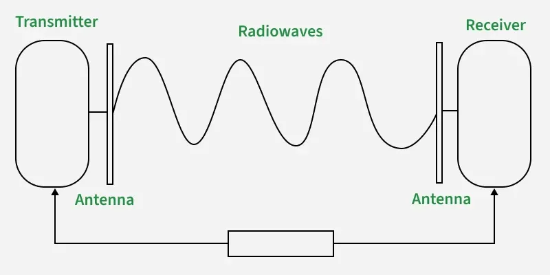
1. Radio Waves
Radio waves are a type of electromagnetic wave that can easily be generated and can propagate through buildings and other obstacles. They do not require line-of-sight between transmitting and receiving antennas, making them highly suitable for broadcast communication and wireless data transmission.
Frequency Range:
3 kHz – 300 GHz
Applications:
AM and FM radio broadcasting, television transmission, cordless phones, and wireless communication.
Types of Radio Waves:
- Shortwave: AM radio broadcasting
- VHF (Very High Frequency): FM radio and television
- UHF (Ultra High Frequency): Television and mobile communication
Components:
- Transmitter: Generates and modulates the signal
- Receiver: Receives and demodulates the signal
2. Microwaves
Micro waves are a form of unguided transmission media that use line-of-sight communication, where the transmitting and receiving antennas must be properly aligned. The transmission range depends on the height of the antennas. Microwaves operate in the frequency range of 1 GHz to 300 GHz and are widely used in mobile communication, satellite links, and television distribution.
Advantages:
- Cost-effective compared to laying physical cables
- No need for land acquisition
- Suitable for communication over difficult terrains and oceans
- Supports high data transmission rates
Disadvantages:
- Less secure without proper encryption
- Susceptible to weather conditions such as rain and fog
- Affected by obstacles due to line-of-sight requirement
- High cost of antenna design, installation, and maintenance

3. Infrared
Infrared waves are used for short-range wireless communication and operate in the frequency range of 300 GHz to 400 THz. They cannot penetrate solid obstacles, which limits their range but helps minimize interference between nearby systems. Infrared waves are commonly used in TV remote controls, wireless keyboards, mice, and printers.

Difference Between Radio Waves, Micro Waves, and Infrared Waves
| Radio Waves | Microwaves | Infrared Waves |
|---|---|---|
| Omnidirectional in nature | Highly directional | Directional, requires line of sight (LOS) |
| Can penetrate buildings and obstacles easily due to low frequency | Poor penetration; line of sight required | Cannot penetrate obstacles |
| Frequency range: 3 kHz – 300 GHz | Frequency range: 1 GHz – 300 GHz | Frequency range: 300 GHz – 400 THz |
| Low security | Medium security (encryption possible) | Relatively high security but limited range |
| Moderate attenuation | Variable attenuation, depends on weather conditions | High attenuation |
| Some frequency bands require government licensing | Most frequency bands are licensed by the government | Generally unlicensed |
| Low to moderate cost | High cost | Low cost |
| Supports long-distance communication | Supports long-distance communication | Suitable only for very short-distance communication |
Causes of Transmission Impairment
Transmission impairment refers to the loss or distortion of signals during data transmission, leading to errors or reduced quality in communication. Common causes include signal distortion, attenuation, and noise all of which can affect the clarity and reliability of transmitted data.
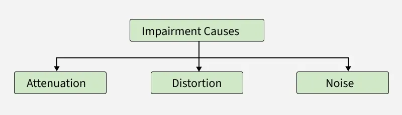
- Attenuation: Loss of signal strength as the signal propagates over a transmission medium due to resistance and energy loss. In analog systems, amplifiers are used to increase signal strength, while in digital communication, repeaters or regenerators are used to restore the original signal.
- Distortion: Occurs when the shape of the transmitted signal changes. This typically happens in composite signals where different frequency components travel at different speeds, causing phase shifts and timing differences at the receiver.
- Noise: It refers to unwanted electrical or electromagnetic signals that interfere with the original signal, potentially corrupting data. Common types of noise include thermal noise, induced noise, crosstalk, impulse noise.
Factors Considered for Designing the Transmission Media
- Bandwidth: It refers to the range of frequencies that a transmission medium can support.
Higher bandwidth allows higher data transmission rates, assuming other factors such as noise and attenuation remain constant. - Transmission Impairment : Transmission Impairment occurs when the received signal differs from the transmitted signal. Signal quality will be impacted as a result of transmission impairment.
- Interference: It is the disturbance of a signal caused by the addition of unwanted signals from external sources such as electromagnetic radiation or neighboring channels. It degrades signal clarity and may result in data corruption.
Applications of Transmission Media in Computer Networks
| Transmission Media | Application |
|---|---|
| Unshielded Twisted Pair (UTP) | Local Area Networks (LAN), telephones |
| Shielded Twisted Pair (STP) | Industrial networks, environments with high interference |
| Optical Fiber Cable | Long-distance communication, internet backbones |
| Coaxial Cable | Cable TV, broadband internet, CCTV |
| Radio | Wireless communication, AM/FM radio, mobile phones |
| Infrared | Remote controls, short-range communication |
| Microwave | Satellite communication, radar, long-distance links |
Planar Transmission Lines
Planar transmission lines are specialized guided structures used to carry high-frequency electrical signals over very short distances within electronic circuits and printed circuit boards. Although they are not used as network communication media, they apply the same fundamental transmission principles used in guided transmission media, such as controlled signal propagation, impedance matching, and interference reduction.
- They follow the same physical layer concepts as guided transmission media.
- Used where very high-frequency signals must be transmitted with minimal loss.
- Help demonstrate how transmission media principles are applied inside electronic hardware.
- Commonly studied in advanced physical-layer and RF design contexts.
Stripline
Stripline is a planar guided transmission structure in which a conducting strip is embedded between two parallel ground planes, allowing high-frequency signals to propagate with excellent shielding and minimal electromagnetic interference.
- Fully enclosed structure provides high EMI immunity
- Supports TEM mode propagation
- Offers better signal isolation and stability
- Used in microwave and high-frequency circuit design
- Suitable for high-performance RF systems
Microstripline
Microstripline is a planar transmission structure consisting of a conducting strip placed on a dielectric substrate with a ground plane on the opposite side, making it widely used for high-frequency signal transmission in printed circuit boards.
- Simple and cost-effective PCB implementation
- Partially exposed fields → lower shielding than stripline
- Supports quasi-TEM mode propagation
- Common in RF circuits, antennas, and microwave PCBs
- Preferred for compact electronic designs