
Building a Temperature Monitoring System (Data Logging from RS485 Devices) Part 1

Objective: Verify whether it is possible to acquire and log values from RS485 devices using the following configuration.
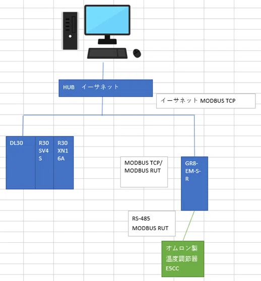

1. First, wire each device as shown in the diagram below.

2. Proceed with the configuration of the DL30 logger.
Set the configuration switch to DL30.

Power on the devices and connect the DL30 to the PC via USB.

Launch the DL30CFG software from the PC.

Click on Communication Settings.

Set to USB, select the COM port connected to the Web Logger 2, and click OK.

Next, set to Network, enter port number 30301 and IP address 192.168.0.10 for the DL30-N, and click OK. (In this case, these numbers are used for the settings, but the factory default settings are IP address 192.168.0.1 and port number 30331.)


Next, click Read (Device) to perform the read operation.


Click on Input/Output.

Click on Slave Settings and configure the connected slave (in this case, the GR8-EM-D-R is the slave).

Next, click on Analog Input (AI). (In this case, we will monitor the current temperature and target temperature of the temperature controller.)


Click on Communication.

Next, click on Modbus/TCP Slave and enter the settings.

Click Record.

Next, click Logging and enter the information.

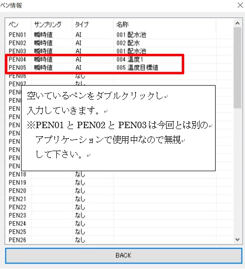

Click "Record" -> "Logging" -> "Header Line 1" to set the header for the logged data.


Set the logging interval.
In this case, we will set it to log at 1-second intervals.

Next, click "Record" -> "Report" to configure the settings for creating reports (daily, monthly, and annual reports).


This completes the configuration for the logger (Model DL30).
The next article, "Building a Temperature Monitoring System (Data Logging from RS485 Devices) Part 2," will cover PC settings and other peripheral device configurations.